


Typical Asphalt Single Roof Mount Sequence
This uses the Unirac Solar Mount system, and one SMA brand string inverter. This mounting system recently qualified as Ontario content, as the mounting system manufacturer set up a manufacturing facility in Ontario. This inverter also recently started producing Ontario content qualified inverters.
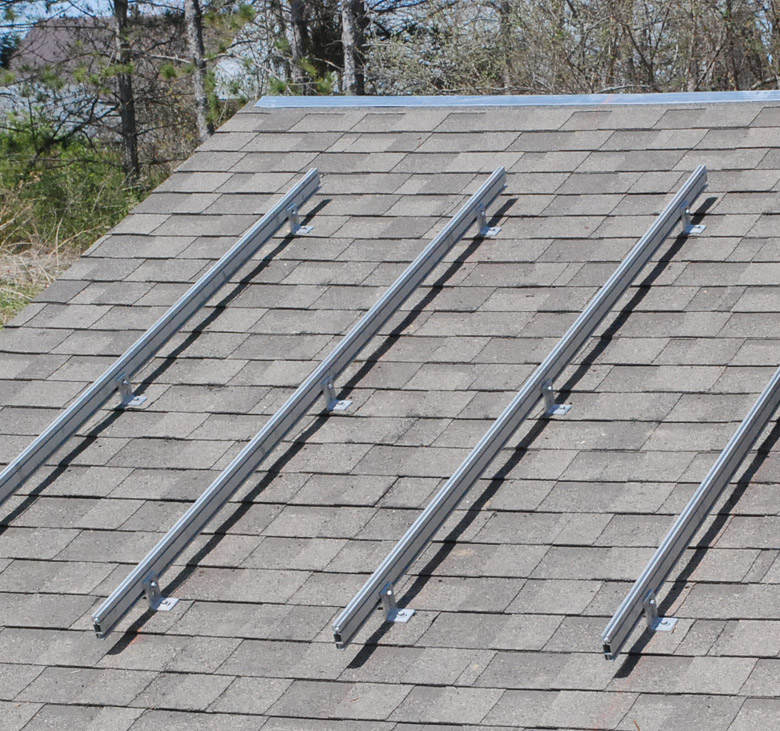
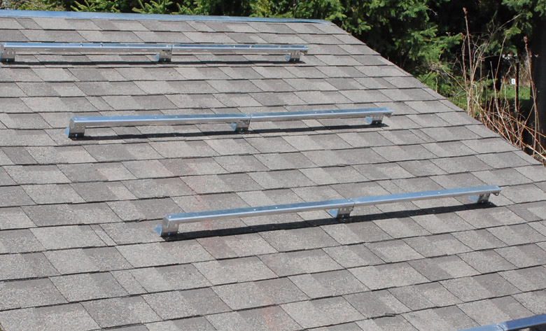
Rails Installed
In the photograph above, the rails have been lag bolted to the roof, spaced to have the lag bolts pierce the plywood roof sheathing and the roof truss member. The top of the lag screw would be coated with a roofing sealant later on, before they are covered up by the panels. This is the simplest possible attachment system and works well for garage roofs and house roofs with good access from underneath to inspect for leaks. The "L foot" bracket is attached first, and then the railis bolted on.
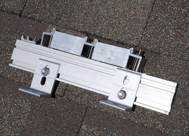
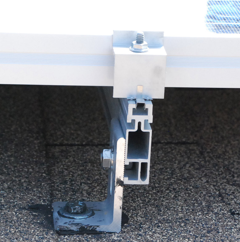
Rail Mounting Extrusion Close up
 This
is a sample assembly, mimicking the mounting of two panels. In this picture each panel is represented by a 2 inch wide block of aluminium. The bolts slide in a channel of the extrusion, and clamp the panel side frame to the extrusion. Note the "Mid Clamp" hold down between the two panels is different from the two "End Clamp" ones. The mounting legs can go into either of two oval slots, to allow for a high or lower clearance of the rail above the roof, and the oval shape of the slots allows compensation for an undulating roof line. This is a top mounted system, which is easiest for larger instalations. The same rail can be used with bottom mounted clamps, ask us for more details.
This
is a sample assembly, mimicking the mounting of two panels. In this picture each panel is represented by a 2 inch wide block of aluminium. The bolts slide in a channel of the extrusion, and clamp the panel side frame to the extrusion. Note the "Mid Clamp" hold down between the two panels is different from the two "End Clamp" ones. The mounting legs can go into either of two oval slots, to allow for a high or lower clearance of the rail above the roof, and the oval shape of the slots allows compensation for an undulating roof line. This is a top mounted system, which is easiest for larger instalations. The same rail can be used with bottom mounted clamps, ask us for more details.
The item on the left end is a "lay in" ground wire clamp. It meets one of the particular electrical code rules that the panels are bonded with a continuous ground, and a panel may be removed from the grounding system without compromising the grounding of all of the remaining panels. The wire can be slid out by loosening a setscrew. Under each of the bolts, and under the ground clip are stainless steels WEEBs that pierce the metal's oxide film and provide a ground path. These are very hard to see, but they are required in this mounting arrangement
Panels attached to Rails
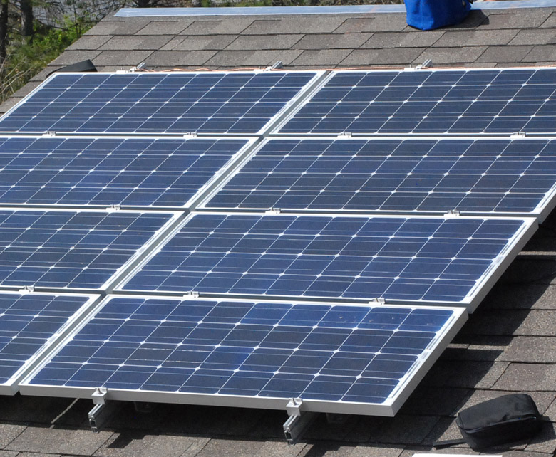
In the top of the picture, you can just see the copper ground wire bonding all the vertical rails together.
Wiring to the Combiner
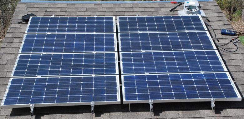
In this picture the combiner box (top right) has been bolted over a hole in the roof, and is in the process of being wired. The wires from the 8 panels are wired in series, and brought to a junction strip inside the combiner box. The combiner may or may not have finger safe fuses. On a bigger system the combiner joins several sets of series wired strings together, before one cable connects the combiner to the DC disconnect switch mounted below. Here a DVM is being used to check the polarity of the leads. The combiner box is designed to look like a rook top vent, and serves to provide a weather tight seal over the hole to pass the wires into the interior of the roof.
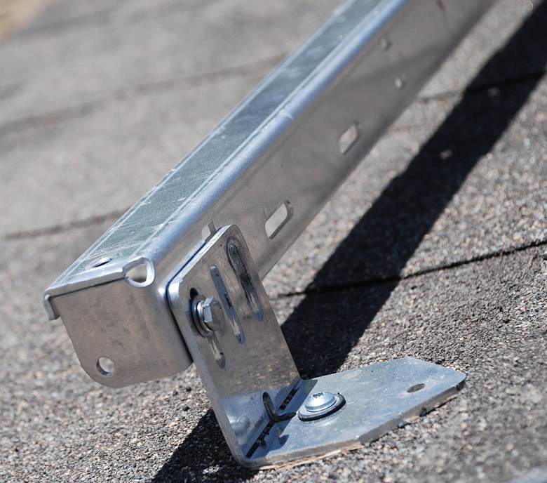
Mounting Rail End View
 Here is an extreme close up of the end of the Unirac rails and End Clamp as seen in the front of the previous photograph. The WEEB is seen compressed beneath the hold down component. The roofing sealant is not very generous in this picture, more is required. One of the duties of this clamping system is to accommodate the expansion and contraction of the panel over the -40C to +35C temperature range of our climate. All of the fasteners are stainless steel. The gap between the rail and the roof encourages air flow, which helps to cool the back of the photocells, and thus produce more electricity. If the panels are mounted too high off the roof, the cooling is better, but the panels are exposed to greater wind forces.
There are addition products that can be used to increase the confidence of the seal of the mounting to the roof. We can supply for example, a product called Quick Mount PV, which uses a metal flashing plate and provides a stud to attach the L foot that you see in the photo above. Quickmount's website refers to an Ashphalt shingle or fiberglass shingle roof as a composition roof. Another available sealing system is made by Ecofasten Solar. This company has products both for ashphalt shingles and for metal roofs. We can supply the GF-1 series components and the Simple Seal for some types of metal roofs. This is not applicable to corrugated roofing often used on older barns.
Inverters and Disconnects
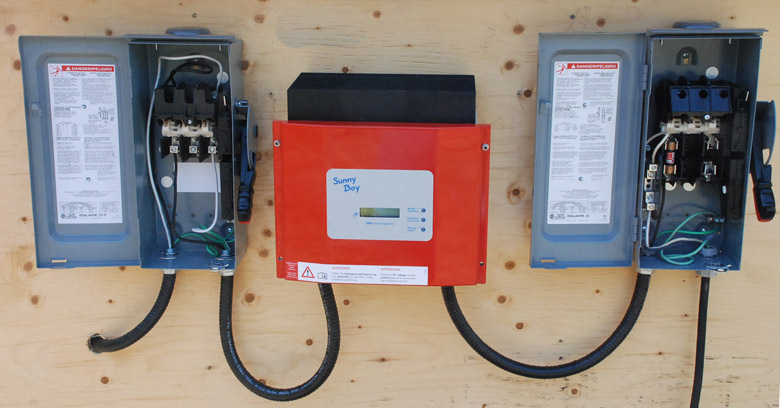 Here is a plywood panel with 3 items mounted to it. These are:
- On the left is a 600V DC rated switch for the DC disconnect
- In the middle, the string inverter, an SMA Sunny Boy
- On the right, the 240VAC rated AC disconnect switch
The covers of the two switches are open, to show more detail, and the switches are in the off position.
The DC disconnect is to isolate the Photovoltaic panel from the inverter, so the inverter can be serviced o0r replaced. The cable on the left of the DC disconnect switch goes to the combiner box on the roof. This goes to the Line side of the DC disconnect switch. The load side of the DC switch goes to the DC side of the inverter. The The DC circuit can operate as high as 600V DC, and thus is the more dangerous side as far as shock hazard and wiring faults. The DC disconnect it typically significantly more expensive then the AC disconnect switch.
The AC disconnect switch is to disconnect the output of the inverter from the Hydro's grid. The right cable from the inverter goes to the load side of the AC disconnect switch. The cable on the right of the AC disconnect switch goes to the line ( 240V AC) and goes to the 2nd meter base (Generation meter) and then to the grid. This needs to be a Service rated switch with either fuses or circuit breaker. Cuiruit breaker type of AC disconnect are not permitted by some municipal utilities.
Distributed Inverter System
This uses a different panel mounting hardware, and Enphase micro-inverters. (One per panel). The particular M190 microinveter is obsolete, and a different wiring system ( plug-and-play Engage Cable system) is used with the newer models.
Here the rails run allong the ridge line, and the panels are installed in a portrait orientation to the sun. These are Sentinel rails, modular and come in the correct length for one panel. Here since the panels are two wide, they are butted together. We can't supply these rails, unless you purchase them as part of a kit with Solgate panels.
Closeup of mounting Rails
 This rail is manufactured by punching and then bending, unlike the previous Unirac system which uses an extrusion. This uses PEM nuts to receive the fastners. It has holes to conveniently mount Enphase inverters, which can be seen in the previous photo. Again this can adjust in height above the roof.
Attaching an Enphase M190 Inverter
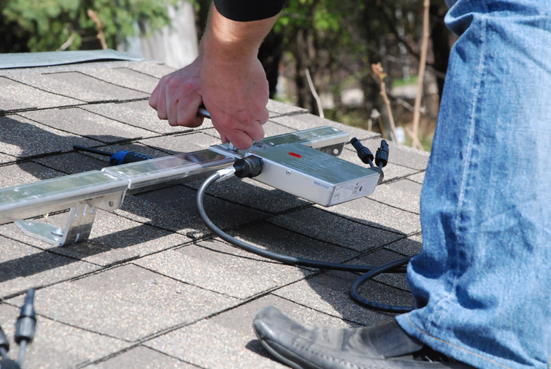
Here a per panel inverter is being fastened to the mounting rail. The inverter will sit underneath the panel. Typically you can't see the inverter from the ground when the installation is complete.
Mounting the first panel
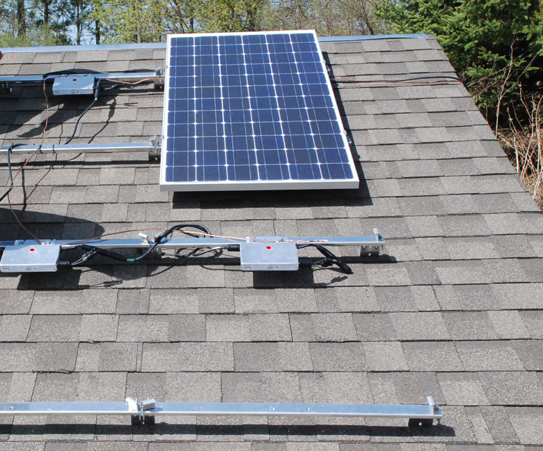
All of the inverters have been installed, the ground wires run to each inverter, and the first panel is clamped in place. The AC output of the inverter is daisy chained to the neighbouring inverter, so there is not a star connection of wires to the combiner. There is only one AC cable and the ground wire for a system of this size, and so from an electrical point nof view, a combiner box is not needed. For bigger sized systems with Enphase inverters, a combiner box will be required, typically it could contain finger safe fuses as well.
One Panel Left to Mount
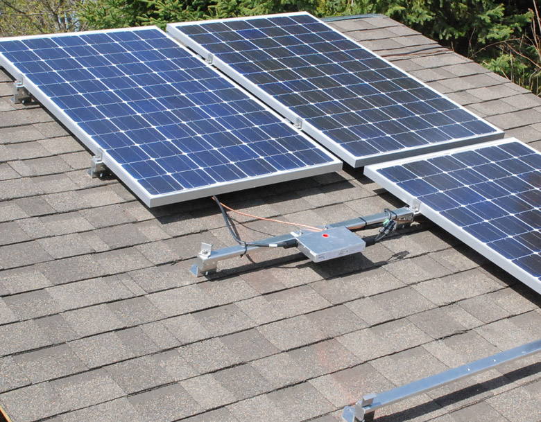
Now only one panel left to mount. The wires are tie-wrapped to ensure that they don't rub on the rough ashphalt shingle and wear away the insulation over time.
The AC disconnect
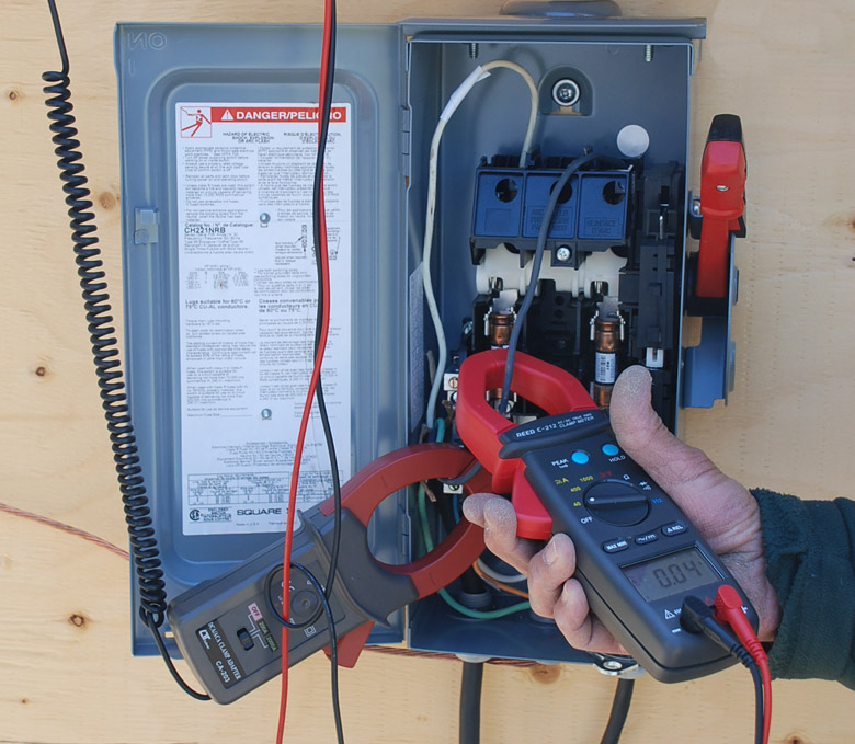
Here the system is connected to the grid, and the output current is being measured. Since the inverters output 240V 60HZ AC, there is no need of a DC disconnect switch, and for an inverter seen in the previous roof. This is simplicity itself. The ESA requires that the inverter's AC output be wired to the load side of the disconnect switch. The line side is wired to the generation meter. The two tools in use are clamp-on ammeters. One is remote reading on a DVM, and the other is hand-held. The meter on the right shows that at this instant, 4A AC is flowing, and at 240VAC that is 0.98kWh. In the background, you can see two cartridge fuses.
For the highly observant, this is not connected to the Hydro's grid, but to an operating off-grid system so that we don't have any issues with permitting. There is no meter, and the wires are not run inside conduit. This was done by me at a training course that I attended. Some of the bigger inverters have a built-in DC disconnect switch so that a stand alone one as shown here is not required.
This is a simpler system for DIY homeowners to understand and to wire. It is also safer to work upon, as there are no high voltage DC circuits, the DC voltage is below the AC line voltage.
This part of the wiring is much simpler than for the 1st roof, and so installers love using this system. On larger array sizes, the string inverter method is more economical based on equipment costs. For an overall system, there are advantages to both. Picking the right choice is part of the system design.