


Home Made Ground Mount Racking
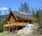
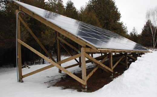
The picture above is a 12 kW ground mount made of preserved wood.
If a DIY person has the time, and is willing to trade a lot of their time as sweat equity to build a solar installation, a ground mount that has a very low material cost can be built in a few of ways. These approached are not used by turnkey installers since these methods are relatively high in labour costs and so if you are paying for labour then the metal kit solutions that bolt together much faster may be more economical. Installers make the majority of their money on markup of the panels, and so faster is most important to them.
Here the various approaches are presented in the order of the lowest cost in materials list first, and sorted in order of increasing material cost.
Pressure Treated Wood Frame
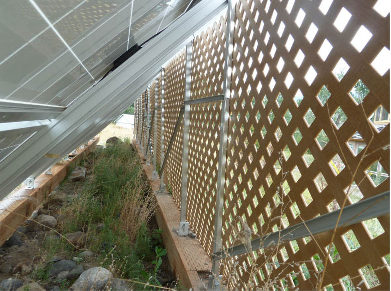
For the DIY person, there is nothing as easy to work with than wood. Usually all the tools required are already in your possession, or can be borrowed from your brother in law. No heavy equipment is required. In the picture above, this was assembled by two people. All of the wood is pressure treated with ACQ, purchased at a local building supply store. The price gets even better if you can catch the lumber on sale.
The photograph above is an example of this, adapted to the sloped site. The general structure of this is illustrated in this drawing, which is designed for a level site.
The North side 6x6 post is 7' 2" long, and the South side concrete post is 2' above grade level. The angle is 30 degrees, which favours summer production. If the slope was increased to 45 degrees, the North post becomes 10' 10" long. All bracing has been omitted in this view, to reduce clutter, the photograph shows how this would be braced. The bracing is easier to do if the front post is made of wood, instead of the 2' high concrete pier.
The foundation is a hole which can be dug by hand, and a Sonotube inserted and filled with concrete and a saddle post set in the top to receive the 6x6 posts. In this case a neighbour with a tractor kindly helped by drilling the holes with a post hole attachment, which took about an hour.
One a level site the front (south) horizontal beam is located just high enough to let snow fall off the panels and provide sufficient ground clearance so the snow does not build up enough to block sunlight. The rear post height determines the slope of the panels, which are normally either latitude -15 degrees or the latitude angle. This is chosen based on shading and the height of trees in the area. The height required for the front can be achieved as in the diagram with extending the concrete foundation tube above the ground, or as seen in the photograph with a 6x6 PT wood post, and a built up horizontal beam. The latter approach requires less accuracy with alignment and the height of the concrete components.
Horizontal 2x4 called purlins support the panel attachment hardware, which can be as simple as a stainless steel nuts and bolt and a fender washer to isolate the aluminium from the Pressure treated wood.
The recommended approach is to use some locally bent brackets to space the panels 1" above the purlins, and to provide less stress when the panels expand and contract. The brackets permit top mounting of the fasteners, which is convenient and faster. If this was done on a regular roof, with no underside access with the panel in place, then top mounting would be essential. These brackets are also part of the grounding system and a lay-in grounding lug is attached to the same stud to ground the brackets, and the panels are grounded to the bracket. The spacing of the studs is done to exactly line up with the mounting holes in the panels.
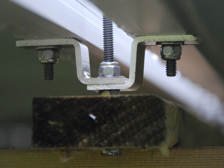
In this photograph, the middle Stainless steel bolt is longer than necessary. The left and right most bolt are each fastening a bracket to a different panel, using one of the the panel's four mounting holes. These two brackets were bolted onto the panel on the ground, with the panel upside down. Then the panel with its four brackets is lifted and lowered into place over the middle bolt. Then a 2nd panel, (the one on the left) is put in place and then the washer and self-locking nut are threaded into place. This is not one of the grounding attachment points and so no lay-in lug is visible.
There are two rafters per group of four panels in portrait orientation. These are drawn showing 16' rafters, but only a 13' length is required, so 14' rafters could be purchased if available.
This method is also very easy to adapt to a sloped site, which is the case in the photograph. On a sloped site, the saddle posts all protrude above the ground about the same height, and the 6x6 posts are cut with a skill saw to make the top of the post level. The horizontal beams are built up in place, and so require no heavy lifting. On a sloped site, this is done to meet the desired snow clearance at the highest end of the slope, and there is an excess of height at the lowest part of the slope.
From the DIY point of view, one of the most attractive features of this is that it contains no commercial components for attaching the panes to the wood frame. This helps to keep the cost down. There are some aluminium brackets that were made at a local machine shop for a little over $100 in total, and about $200 for stainless steel fasteners.
If you choose to by panels from us, we can supply CAD drawings for this structure, which you can have reviewed by a structural engineer for suitability for the wind and snow load in you area. The same person would also be able to tell you how deep to set the post footings, and how far apart they should be for your local conditions.
A tour of this installation is available upon request by appointment. This is located in the Almonte area.
Pressure Treated Wood Triangle with Aluminium Channel
This particular example is designed for a climate with less snow than Ontario, but it is a good example of a hybrid approach. This example is mounting one panels high in portrait orientation.
 There are a few things I need to point out. I would also use pressure treated wood (PT) , and so you need to use appropriate fasteners suitable for ACQ treated lumber. Use a stainless steel washer underneath the Ironridge L foot and use a stainless steel lag bolt. I would not embed the rear post on concrete, but would put in a saddle post and as a result you would need diagonal cross bracing at the back. The preserved wood will last longer above ground. Initially this will be much stronger, but the concrete may fail with time due to the wood expanding and contracting with humidity changes.
With ACQ treated PT lumber, a gang nail plate may not last for the life of the project, unless you can get it in hot dipped or stainless which I can't find. Here a structural nailing plate was used. Consider using either pressure treated plywood attached with screws (lots) instead, or a hot dip galvanized structural nailing plate.
You could use this system for two panels high in portrait and still not exceed 16' lengths of lumber. I suggest that the bottom of the panel be located further up from the ground, to give more height above the snow.
The explanation of the original web site is nicely done and can be read in full at builditsolar. You would need 5 of these for a maximum size grid tied installation. This method would be good for a flat site, but difficult on a sloped site as above, as each piece of wood would be a different length.
The N - S spacing of the wood supports is determined by the rail manufacturer's specification for loading with your local wind and snow load conditions. Here the heaviest duty rails would permit the greatest spacing, and thus reduce the time to built this structure. With Unirac's SM rails this would be about 4', and with Ironridge's XLR rail it would be 5.5' for 40 lb/ft2 snow load and 90 MPH winds.
The estimated cost of this will be higher than the previous example due to the use of the extruded aluminium roof racking hardware. However the time to build this should be less. This has a lower wood material cost due to the use of less length and 4x4 instead of 6x6. However the cost of the extruded rail and accessories to support and attach the panels is about the same as the entire structure illustrated in the first method.
Wood and Aluminium Extrusion Combination
This uses a preserved wood base of two parallel beams at the same height, and uses a flat roof style arrangement of aluminium extrusions to support the panels on an angle. If you have a flat site, then put in two horizontal wood rails, but unlike in the first example these will be at the same height, just high enough to let snow fall off the panels and provide sufficient ground clearance so the snow does not build up enough to block sunlight. Then you put an L-foot on the bottom horizontal member, using a lag bolt and a stainless Steel fender washer between the ACQ treated pressure treated wood and the bottom of the L foot. Do the same on the North rail, and then use a SM rail in the N _ S direction bolted to the L foot on the South rail, and then use another length of SM rail extending vertically, and use a splice plate to couple the two rails together at the top. Put in two N - S SM rails per panel and mount several panels in landscape orientation. Do this for a maximum of two high.
This does not require drilling any holes in metal, and if you are careful to support the panels correctly, you even make this work as a crude type of seasonal tilt adjustment. Changing the tilt will require at least two people, and you will have to take the tilt into account when you run the PV wires. The wires can't be run in the E -W direction except at the base.
For a Unirac document on this topic search for "High profile tilt legs ii205" on Unirac's web site. The lower L feet go on the south beam and the tilt strut  anchors to a L foot on the North beam. The adjustable tilt legs described in the Unirac document are not available as Ontario content. You can make your own fixed length ones from square extrusions, or U channel. You can also use additional length of Unirac SM rail which would be more expensive. I do not recommend using more than 2 panels per rail using this scheme, unless also adding one extra tilt leg from the North beam for 3 panels, and two for four panels. Ironridge has an Ontario content tilt legs specifically for this application. The panels are drawn in landscape orientation at 39" high, a typical dimension for 230W panels. The concrete posts are 24" above grade, which results in the lowest panel's edge about 2' 9" above grade.
For Eastern Ontario even two panels exceeds the rating for the Unirac SM rails without bracing. The SM HD rails would be stronger, but they are not available as Ontario content, however I can obtain them for non-FIT applications by special order. The Ironridge XLR rails are heavier duty and would be stronger for two portrait oriented panel applications. Both manufacturers recommend using cantilever at both ends to reduce the unsupported distance. That can easily be done with this system, but it puts the lower edge of the bottom panel closer to the snow. That can bring the unsupported rail length within the recommended unsupported span distance.
A practical view of this implemented for a more southerly climate is:
 In Ontario the bottom of the panels need to be higher off the ground. The concrete piers could stick out of the ground 2', or the panels would not be mounted on the bottom part of the Unirac SM rail, and thus more rail would be used, and it would be further between support points and so more highly stressed (not recommended). Note the diagonal bracing on the North side struts, this is highly recommended. A hint, the 2" extrusion or U channel could be purchased at a scrap yard to help moderate the cost.
This method uses more extruded solar mounting rails and the vertical struts of aluminium. Thus this will cost more than the preceding method due to the additional amount of aluminium used. In fact, this uses exactly the same amount of aluminium extrusion as a roof mount to hold the same number of panels. Effectively this more than doubles the material cost from the first method using all preserved wood construction.
Pipe Handrail Components
You can make two round horizontal beams out of 2" schedule 40 aluminium or galvanized steel pipe and support them with posts set in concrete, and make two rails, a high one at the N side and lower at the S side to support the panels and create the slope. Each rails runs in the E -W direction. Before you read further, look at this this website to see the top two pictures, which illustrate this product in its intended use as a railing system. A tee fitting L25-9 attaches it to the top of the vertical post. You then can use hot dip galvanized steel or aluminium channel or aluminium rooftop extrusions such as Unirac's SM rails to provide N - S rails onto which you attach the panels. If you make the panels only one high, then you could mount the panels to the two horizontal round top rails by drilling a hole through the pipe at the right angle and then using a stainless steel 1/4 - 20 bolt through the rail and up into the panel's mounting hole. Aluminium and stainless steel are compatible enough that this combination is used almost exclusively in solar installations.
You lay out the location of the poles so that they don't occur under any of the panel edges.
Also provide some diagonal bracing, using the same pipe system.
If you make the panels 2 or more high, and then use the Unirac SM type of extruded rails, then the other item that you will need to improvise is a clamp to attach the extrusion to the round pipe. A muffler clamp and a Unirac L foot could work, use a stainless steel or hot dip galvanized muffler clamp to avoid corrosion.
I don't recommend making a mounting system of this type more than 3 high with this material, without consulting a Structural Engineer.
For more information about pipe railing products see this link from a US supplier that has a nice website with pictures and prices.
The schedule 40 pipe is available from many sources, and you should be able to find a local supplier. You can choose aluminium or galvanized, and make the N - S U channel out of the same material. The 2" size is recommended. This US site has a lot of useful information about that type of pipe, including US pricing.
An example of this concept north of Barrie can be seen in this image, even though it does not rigorously follow this idea. This was installed as a turnkey system, and we had nothing to do with it, other than visiting the owner on business.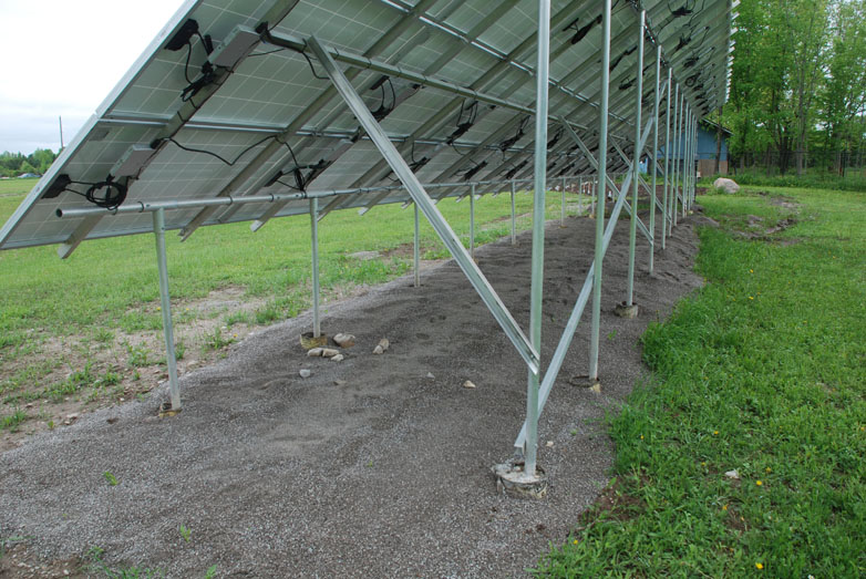
It uses U channel and U bolts to attach the channel in the N - S direction to the top of the horizontal pipe. The use of the U channel reduces the number of parts, but increases the number of holes that need to be drilled. Do NOT drill any holes in the panels, as this will invalidate all warranty on the panels. Instead use the four mounting holes that are provided by the panel, which expect 1/4" fasteners.
You can see some bracing to support the N - S channels in a third place. This is certainly called for with four panels high.
Conclusion: The schedule 40 2" pipe in aluminium or steel is in the range of $10 a foot. Pressure treated wood is $1 to $2 a foot, and so even though this metal pipe appears to use less materials, it would cost a lot less to do it with wood by using any one one of the examples above. This method is included because it is a fairly obvious method, and seems at first glance to use a minimum amount of material and so would be thought to be low cost. This is practical to build, and uses only material that can be sourced locally, with the exception of the tee fitting.